01 MIPI C-PHY Physical layer transmitter simulation / MIPI C-PHY Generator
This is the test solution provided by METMET Technology for R&D testing and mass production testing of MIPI C-PHY receivers. You can use MET's METER™ series arbitrary waveform generator MWG-243A, combined with waveform generation software for simulating C-PHY transmitters and test management software for C-PHY receiver testing, to generate MIPI C-PHY test signals and simulate a MIPI C-PHY transmitter, thereby testing the MIPI C-PHY receiver.
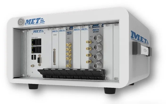
MET MIPI C-PHY Generator Solution capabilities:
★ With a maximum sampling rate of 24 GSa/s
★ Generate waveforms according to MIPI C-PHY standard
★ With up to 16-bit vertical resolution
★ Supports waveform generation for different MIPI C-PHY modes, such as low power (LP) and high speed (HS)
★ Allows users to configure parameters such as code type, rise/fall time, symbol rate, wire level, etc.
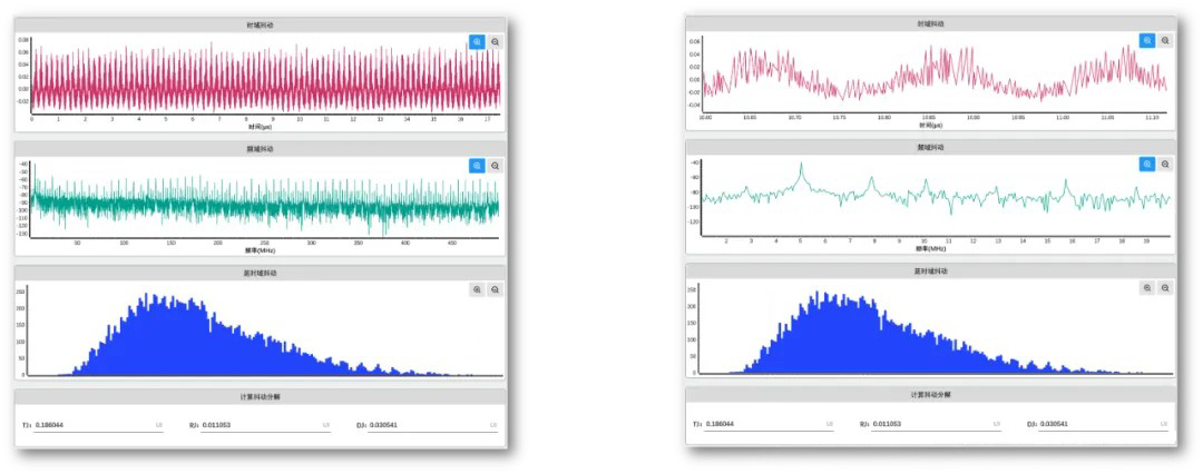
★ Supports jitter injection function, such as periodic jitter/random jitter
★ Supports noise injection function, such as sinusoidal noise
★ Supports channel embedding function, such as .snp file embedding
★ Supports waveform generation for receiver margin testing
02 MIPI C-PHY // Background
MIPI D-PHY/C-PHY/A-PHY, etc. are physical layer interfaces launched by MIPI Alliance (Mobile Industry Processor Interface Alliance), which are mainly used in various applications in mobile devices, such as cameras and displays. MIPI C-PHY was originally designed to meet the growing demand for data transmission, while taking into account the strict restrictions on power consumption and size of mobile devices. In addition to its widespread use in mobile devices, MIPI C-PHY is also widely used in multiple industries such as automotive and medical. Whether it is the D-PHY℠ interface on the display link, the C-PHY℠ interface on the camera link, or the M-PHY℠ interface on the memory link, they are all typical application scenarios of the MIPI protocol.
In general, MIPI C-PHY, as a new physical layer interface, is gradually changing the way data is transmitted in mobile devices and other industries with its advantages such as high speed, low power consumption and high flexibility.
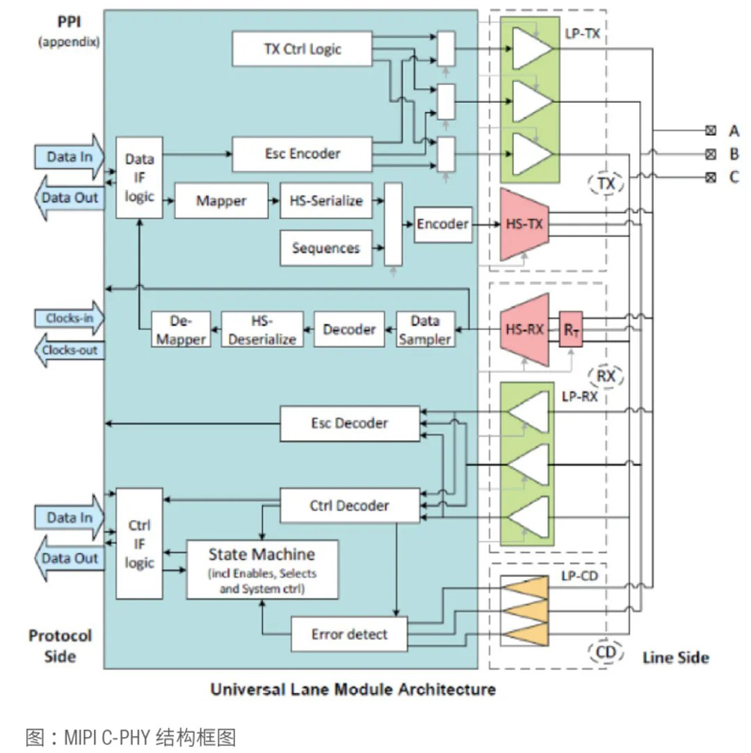
MIPI C-PHY uses three-wire differential output at the physical layer. Each Lane (also called Trio) has three wires, as shown in the figure above. C-PHY can support transmission of up to three Lanes at the same time.
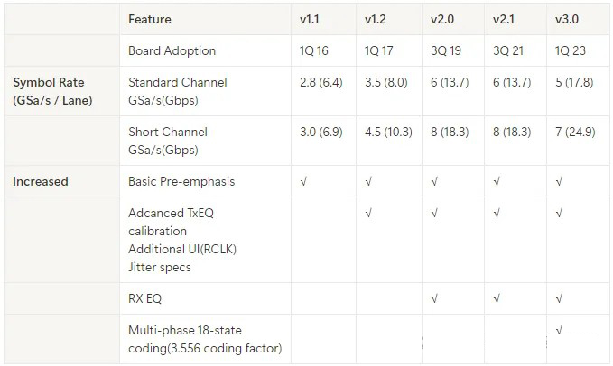
Taking the V2.1 standard as an example, the data transmission rate of a Lane is 6 GSa/s, and each symbol carries 2.28 bits of information (the minimum transmission unit of C-PHY is 16 bits, and 7 symbols carry 16 bits of information, so the amount of information per symbol is 2.28 bits). Therefore, the data transmission rate of a single Lane is 13.7 Gbps, and the transmission rate of three Lanes can reach 41 Gbps when transmitting simultaneously, which is a very significant advantage.
The evolution roadmap of key parameters of different MIPI C-PHY protocol versions is shown in the following table.
03 MET - MET Technology Testing Solutions // Introduction
PART/1 Test architecture
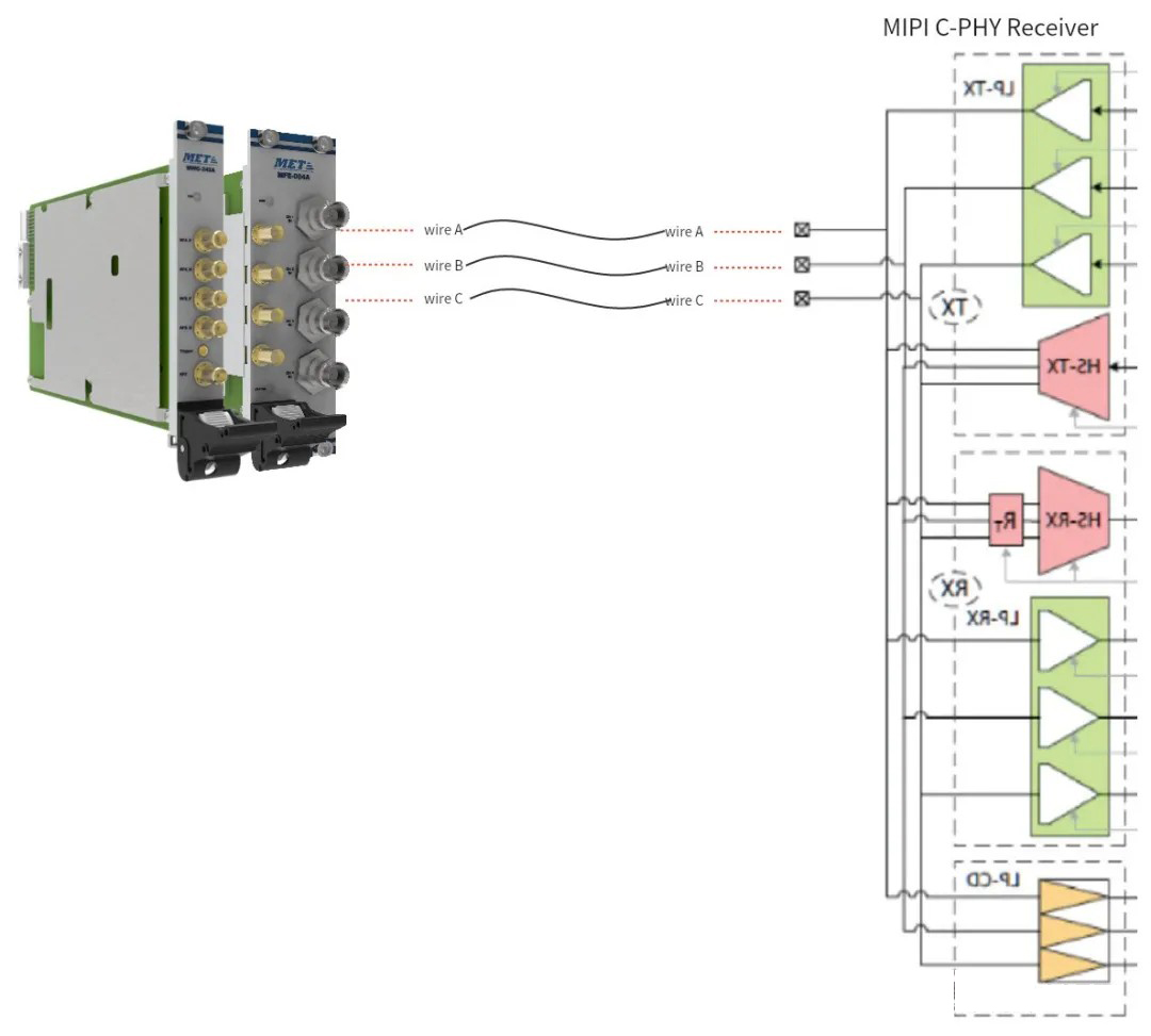
PART/2 Hardware composition of C-PHY receiver test system
MET provides high-precision hardware support for MIPI transmitter simulation and MIPI receiver testing
MET's METER™ series arbitrary waveform generator MWG-243A has a maximum sampling rate of 24 GSa/s and a maximum vertical resolution of 16 bits. Usually, AWG is used to generate waveforms, so the sampling rate is at least 3 times the pattern rate. Taking the MIPI C-PHY v2.1 standard as an example, the symbol rate is 6 GSa/s, and the AWG sampling rate needs to be at least 18 GSa/s. MET's METER™ series AWG can meet the protocol rate requirements of different versions of MIPI C-PHY, providing high-precision hardware support for your testing and system construction.
PART/3 Measurement software for C-PHY receiver test system
MET provides powerful and flexible measurement software for various test scenarios and usage requirements:
- Waveform generation software for simulating C-PHY transmitters
- Production test software for C-PHY receiver testing
Based on MET's MIPI C-PHY receiver test solution, you can generate MIPI C-PHY test signals and simulate a MIPI C-PHY transmitter to test the MIPI C-PHY receiver. You can easily configure the measurement software and adjust the configuration parameters you need to complete the test process.
- Generate waveforms according to MIPI C-PHY standard
- Supports waveform generation for different MIPI C-PHY modes, such as low power (LP) and high speed (HS)
- Allows users to configure parameters such as code type, rise/fall time, symbol rate, wire level, etc.
- Support jitter injection function, such as periodic jitter/random jitter
- Supports noise injection function, such as sinusoidal noise
- Support channel embedding function, such as: .snp file embedding
- Supports waveform generation for receiver margin testing
PART/4 Performance Display
⚪Jitter injection and jitter analysis capabilities demonstrated
⚪Signal eye diagram display
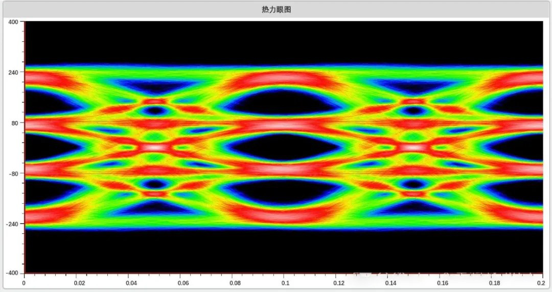
Figure: 12 Gbps PAM4 signal eye diagram
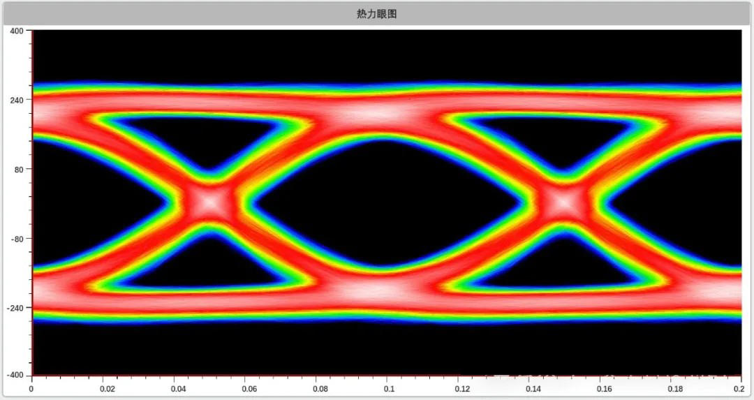
Figure: 8Gbps NRZ signal eye diagram
Share:
News Center
2025-03-20News Center
2025-03-05News Center
2025-02-20


10th Floor, Building N4, Suzhou 2.5 Industrial Park, Dongchang Road, Suzhou Industrial Park, Suzhou City, Jiangsu Province
Copyright © Suzhou MET Technology Co., Ltd.- All Rights Reserved Web design